Monday, 9 February 2015

Cisco VSS: Failure scenarios

In the last article, I explained how to configure the Cisco 6500 in VSS configuration, but how does the VSS reacts during a failure? There are three possible scenarios:
  1. Link failure within a multichassis Cisco etherchannel link
  2. Active supervisor engine failure
  3. VSL failure
Scenario #1: Link failure within a multichassis Cisco etherchannel link
Availability is not affected for those data flows that do not use the failed link. For those traffic flows that use the failed link, the effect consists of the time it takes to detect the link failure and reprogram the indices within the system.
VSS-link-fail-1
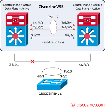
When all link connected to a Cisco 6500 are failed (in this case there is only one link for each 6500), the port bundle is converted from a multichassis Cisco EtherChannel link to a standard Cisco EtherChannel link, and is treated as a single-homed port.
VSS-link-fail-2
Remember: The supervisor engine on the active virtual switch is also responsible for programming the hardware forwarding information onto all the distributed forwarding cards across the entire Cisco Virtual Switching System. It also programsthe policy feature card on the standby virtual switch supervisor engine. For these reasons, both the active and the hot-standby supervisor engine PFCs are active, and are used to perform packet lookups for centralized lookups on each chassis.
For these reasons, if a packet reaches the standby virtual switch there are two different behaviours:
  • If a packet is software switched, the packet is sent to the active virtual switch through the VSL.
  • If a packet is hardware switched, the packet is managed by the standby virtual switch.

Scenario #2: Active supervisor engine failure
The standby supervisor engine can detect the failure of the active supervisor engineusing one of the following methods:
  • VSL Protocol (VSLP)
  • Cisco Generic Online Diagnostics (GOLD) failure event
  • Full VSL link down

VSS-Supervisor-Failure-1
Upon detecting the failure of the active supervisor, the hot-standby supervisor engine performs an SSO switchover and assumes the role of the active supervisor.
VSS-Supervisor-Failure-2
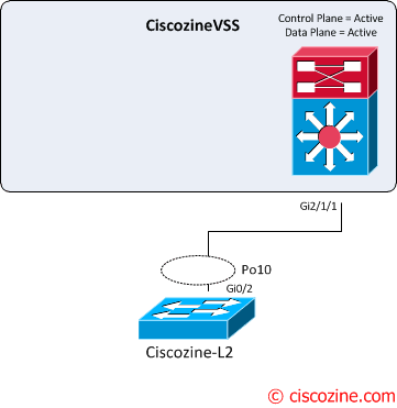
During the transition, there is a disruption to the traffic that must transition awayfrom the failed chassis. The duration of traffic disruption is determined by the time required to transition the role of the hot-standby supervisor engine to the active supervisor engine, and for the neighboring device to modify its path selection to the newly active chassis.

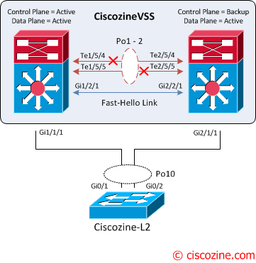
Scenario #3: VSL failure
The failure of a single VSL link is discovered by the active supervisor engine, either through a link-down event or through the failure of periodic VSLP messages sent across the link to check the VSL link state. Availability is not affected for those data flows that do not use the VSL.
VSS-1-fault
The active supervisor engine discovers the failure of the “entire” VSL either through a link-down event or through the failure of the periodic VSLP messages sent across the member links to check the VSL link status. From the perspective of the active virtual switch chassis, the standby virtual switch is lost. The standby virtual switch chassis also views the active virtual switch chassis as failed and transitions to active virtual switch state through an SSO switchoverThis scenario is known as a dual-active scenario and the duplication of this configuration can possibly have adverse effects to the network topology and traffic.
To avoid this disruptive scenario, you should configure one of these methods:
  • Enhanced PAgP
  • Layer 3 BFD
  • Fast Hello
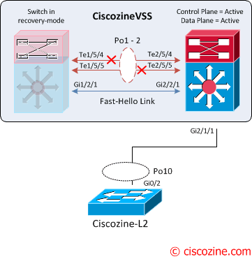
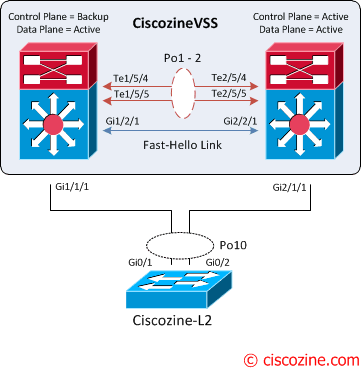
In this case the Fast hello link method is implemented.
VSS-2-fault
Upon detecting the dual-active condition, the original active chassis enters intorecovery mode and brings down all of its interfaces except the VSL and nominated management interfaces. This effectively removes the device from the network.
VSS-recovery-1
You will see the following messages on the active virtual switch to indicate that a dual-active scenario has occurred:
CiscozineVSS#
Jan 23 11:57:37.647: %VSLP-SW1_SP-3-VSLP_LMP_FAIL_REASON: Te1/5/5: Link down
Jan 23 11:57:37.647: %VSLP-SW1_SP-2-VSL_DOWN: Last VSL interface Te1/5/5 went down
Jan 23 11:57:37.735: %VSLP-SW1_SP-2-VSL_DOWN: All VSL links went down while switch is in ACTIVE role
Jan 23 11:57:37.799: %LINEPROTO-SW1_SP-5-UPDOWN: Line protocol on Interface TenGigabitEthernet1/5/5, changed state to down
Jan 23 11:57:37.803: %LINEPROTO-SW1_SP-5-UPDOWN: Line protocol on Interface Port-channel1, changed state to down
Jan 23 11:57:37.803: %LINK-SW1_SP-3-UPDOWN: Interface Port-channel1, changed state to down
Jan 23 11:57:37.807: %LINK-SW1_SP-3-UPDOWN: Interface TenGigabitEthernet1/5/5, changed state to down
Jan 23 11:57:37.875: %DUAL_ACTIVE-SW1_SP-1-DETECTION: Fast-hello running on Gi1/2/1 detected dual-active condition
Jan 23 11:57:37.875: %DUAL_ACTIVE-SW1_SP-1-RECOVERY: Dual-active condition detected: Starting recovery-mode, all non-VSL and non-excluded interfaces have been shut down
CiscozineVSS(recovery-mode)#

The following messages on the standby virtual switch console indicate that a dual-active scenario has occurred:
CiscozineVSS-sdby#
Jan 23 11:57:37.647: %VSLP-SW2_SPSTBY-3-VSLP_LMP_FAIL_REASON: Te2/5/5: Link down
Jan 23 11:57:37.647: %VSLP-SW2_SPSTBY-2-VSL_DOWN:   Last VSL interface Te2/5/5 went down
Jan 23 11:57:37.651: %VSLP-SW2_SPSTBY-2-VSL_DOWN:   All VSL links went down while switch is in Standby role
Jan 23 11:57:37.651: %DUAL_ACTIVE-SW2_SPSTBY-1-VSL_DOWN: VSL is down - switchover, or possible dual-active situation has occurred
Jan 23 11:57:37.651: %PFREDUN-SW2_SPSTBY-6-ACTIVE: Initializing as Virtual Switch ACTIVE processor
Jan 23 11:57:39.559: %LINK-3-UPDOWN: Interface TenGigabitEthernet2/5/5, changed state to down
Jan 23 11:57:39.559: %LINEPROTO-SW2_SP-5-UPDOWN: Line protocol on Interface TenGigabitEthernet2/5/5, changed state to down
Jan 23 11:57:40.579: %OIR-SW2_SP-6-INSREM: Switch 1 Physical Slot 1 - Module Type LINE_CARD  removed 
Jan 23 11:57:40.899: %OIR-SW2_SP-6-INSREM: Switch 1 Physical Slot 2 - Module Type LINE_CARD  removed 
Jan 23 11:57:40.991: %OIR-SW2_SP-6-INSREM: Switch 1 Physical Slot 3 - Module Type LINE_CARD  removed 
Jan 23 11:57:41.107: %OIR-SW2_SP-6-INSREM: Switch 1 Physical Slot 5 - Module Type LINE_CARD  removed 
Jan 23 11:58:00.335: %VSLP-SW2_SP-2-VSL_DOWN:   All VSL links went down while switch is in ACTIVE role
CiscozineVSS#

This is confirmed by the show command:
CiscozineVSS#show switch virtual redundancy 
                  My Switch Id = 2
                Peer Switch Id = 1
        Last switchover reason = active unit removed
    Configured Redundancy Mode = sso
     Operating Redundancy Mode = sso

Switch 2 Slot 5 Processor Information :
-----------------------------------------------
        Current Software state = ACTIVE
       Uptime in current state = 0 minutes
                 Image Version = Cisco IOS Software, s72033_rp Software (s72033_rp-ADVENTERPRISEK9-M), Version 15.1(2)SY, RELEASE SOFTWARE (fc4)
Technical Support: http://www.cisco.com/techsupport
Copyright (c) 1986-2013 by Cisco Systems, Inc.
Compiled Wed 04-Sep-13 13:05 by prod_rel_team
                          BOOT = bootdisk:s72033-adventerprisek9-mz.151-2.SY.bin,12;
        Configuration register = 0x2102
                  Fabric State = ACTIVE
           Control Plane State = ACTIVE

Peer information is not available because 
it is in 'DISABLED' state
CiscozineVSS#

When the VSL is restored, the following messages are displayed on the console and the switch in recovery mode (previous active virtual switch) reloads:
Jan 26 13:23:34.877: %DUALACTIVE-1-VSL_RECOVERED: VSL has recovered during dual-active situation: Reloading switch 1
Jan 26 13:23:34.909: %SYS-5-RELOAD: Reload requested Reload Reason: Reload Command.
VSS-recovery-2
After the reloading, the VSS is recovered; the control plane remains active on the previous standby virtual switch. To force a switchover use the command:
redundancy force-switchover

Wednesday, 4 February 2015

Example: Configuring an OSPF Router Identifier

This example shows how to configure an OSPF router identifier.

Requirements
Overview
Configuration
Verification
Requirements
Before you begin:

Identify the interfaces on the routing device that will participate in OSPF. You must enable OSPF on all interfaces within the network on which OSPF traffic is to travel.
Configure the device interfaces. See the Junos OS Network Interfaces Library for Routing Devices or the Junos OS Interfaces Configuration Guide for Security Devices.
Overview
The router identifier is used by OSPF to identify the routing device from which a packet originated. Junos OS selects a router identifier according to the following set of rules:

By default, Junos OS selects the lowest configured physical IP address of an interface as the router identifier.
If a loopback interface is configured, the IP address of the loopback interface becomes the router identifier.
If multiple loopback interfaces are configured, the lowest loopback address becomes the router identifier.
If a router identifier is explicitly configured using the router-id address statement under the [edit routing-options] hierarchy level, the above three rules are ignored.

Note: If the router identifier is modified in a network, the link-state advertisements (LSAs) advertised by the previous router identifier are retained in the OSPF database until the LSA retransmit interval has timed out.

If the router identifier is not configured explicitly and an interface IP address is used as the router identifier, the established OSPF adjacency flaps when the interface goes down, or when it is brought back into the network. When the interface is brought back into the network, or a new interface is introduced into the network, the router identifier is selected again based on the rules stated above. Hence, it is strongly recommended that you explicitly configure the router identifier under the [edit routing-options] hierarchy level to avoid unpredictable behavior if the interface address on a loopback interface changes.

Note: The router identifier behavior described here holds good even when configured under [edit routing-instances routing-instance-name routing-options] and [edit logical-systems logical-system-name routing-instances routing-instance-name routing-options] hierarchy levels.

In this example, you configure the OSPF router identifier by setting its router ID value to the IP address of the device, which is 177.162.4.24.

Configuration
CLI Quick Configuration
To quickly configure an OSPF router identifier, copy the following command and paste it into the CLI.

[edit]
set routing-options router-id 177.162.4.24
Step-by-Step Procedure
To configure an OSPF router identifier:

Configure the OSPF router identifier by entering the [router-id] configuration value.
[edit]
user@host# set routing-options router-id 177.162.4.24
If you are done configuring the device, commit the configuration.
[edit]
user@host# commit

Results
Confirm your configuration by entering the show routing-options router-id command. If the output does not display the intended configuration, repeat the instructions in this example to correct the configuration.

user@host# show routing-options router-id
router-id 177.162.4.24;


Verification
After you configure the router ID and activate OSPF on the routing device, the router ID is referenced by multiple OSPF operational mode commands that you can use to monitor and troubleshoot the OSPF protocol. The router ID fields are clearly marked in the output.

Understanding OSPF Designated Router

Large LANs that have many routing devices and therefore many OSPF adjacencies can produce heavy control-packet traffic as link-state advertisements (LSAs) are flooded across the network. To alleviate the potential traffic problem, OSPF uses designated routers on all multiaccess networks (broadcast and nonbroadcast multiaccess [NBMA] networks types). Rather than broadcasting LSAs to all their OSPF neighbors, the routing devices send their LSAs to the designated router. Each multiaccess network has a designated router, which performs two main functions:

Originate network link advertisements on behalf of the network.
Establish adjacencies with all routing devices on the network, thus participating in the synchronizing of the link-state databases.
In LANs, the election of the designated router takes place when the OSPF network is initially established. When the first OSPF links are active, the routing device with the highest router identifier (defined by the router-id configuration value, which is typically the IP address of the routing device, or the loopback address) is elected the designated router. The routing device with the second highest router identifier is elected the backup designated router. If the designated router fails or loses connectivity, the backup designated router assumes its role and a new backup designated router election takes place between all the routers in the OSPF network.

OSPF uses the router identifier for two main purposes: to elect a designated router, unless you manually specify a priority value, and to identify the routing device from which a packet is originated. At designated router election, the router priorities are evaluated first, and the routing device with the highest priority is elected designated router. If router priorities tie, the routing device with the highest router identifier, which is typically the routing device’s IP address, is chosen as the designated router. If you do not configure a router identifier, the IP address of the first interface to come online is used. This is usually the loopback interface. Otherwise, the first hardware interface with an IP address is used.

At least one routing device on each logical IP network or subnet must be eligible to be the designated router for OSPFv2. At least one routing device on each logical link must be eligible to be the designated router for OSPFv3.

By default, routing devices have a priority of 128. A priority of 0 marks the routing device as ineligible to become the designated router. A priority of 1 means the routing device has the least chance of becoming a designated router. A priority of 255 means the routing device is always the designated router.

Understanding OSPF Areas

In OSPF, a single autonomous system (AS) can be divided into smaller groups called areas. This reduces the number of link-state advertisements (LSAs) and other OSPF overhead traffic sent on the network, and it reduces the size of the topology database that each router must maintain. The routing devices that participate in OSPF routing perform one or more functions based on their location in the network.

This topic describes the following OSPF area types and routing device functions:

Areas
Area Border Routers
Backbone Areas
AS Boundary Routers
Backbone Router
Internal Router
Stub Areas
Not-So-Stubby Areas
Transit Areas
Areas

An area is a set of networks and hosts within an AS that have been administratively grouped together. We recommend that you configure an area as a collection of contiguous IP subnetted networks. Routing devices that are wholly within an area are called internal routers. All interfaces on internal routers are directly connected to networks within the area.

The topology of an area is hidden from the rest of the AS, thus significantly reducing routing traffic in the AS. Also, routing within the area is determined only by the area’s topology, providing the area with some protection from bad routing data.

All routing devices within an area have identical topology databases.

Area Border Routers

Routing devices that belong to more than one area and connect one or more OSPF areas to the backbone area are called area border routers (ABRs). At least one interface is within the backbone while another interface is in another area. ABRs also maintain a separate topological database for each area to which they are connected.

Backbone Areas

An OSPF backbone area consists of all networks in area ID 0.0.0.0, their attached routing devices, and all ABRs. The backbone itself does not have any ABRs. The backbone distributes routing information between areas. The backbone is simply another area, so the terminology and rules of areas apply: a routing device that is directly connected to the backbone is an internal router on the backbone, and the backbone’s topology is hidden from the other areas in the AS.

The routing devices that make up the backbone must be physically contiguous. If they are not, you must configure virtual links to create the appearance of backbone connectivity. You can create virtual links between any two ABRs that have an interface to a common nonbackbone area. OSPF treats two routing devices joined by a virtual link as if they were connected to an unnumbered point-to-point network.

AS Boundary Routers

Routing devices that exchange routing information with routing devices in non-OSPF networks are called AS boundary routers. They advertise externally learned routes throughout the OSPF AS. Depending on the location of the AS boundary router in the network, it can be an ABR, a backbone router, or an internal router (with the exception of stub areas). Internal routers within a stub area cannot be an AS boundary router because stub areas cannot contain any Type 5 LSAs.

Routing devices within the area where the AS boundary router resides know the path to that AS boundary router. Any routing device outside the area only knows the path to the nearest ABR that is in the same area where the AS boundary router resides.

Backbone Router

Backbone routers are routing devices that have one or more interfaces connected to the OSPF backbone area (area ID 0.0.0.0).

Internal Router

Routing devices that connect to only one OSPF area are called internal routers. All interfaces on internal routers are directly connected to networks within a single area.

Stub Areas

Stub areas are areas through which or into which AS external advertisements are not flooded. You might want to create stub areas when much of the topological database consists of AS external advertisements. Doing so reduces the size of the topological databases and therefore the amount of memory required on the internal routers in the stub area.

Routing devices within a stub area rely on the default routes originated by the area’s ABR to reach external AS destinations. You must configure the default-metric option on the ABR before it advertises a default route. Once configured, the ABR advertises a default route in place of the external routes that are not being advertised within the stub area, so that routing devices in the stub area can reach destinations outside the area.

The following restrictions apply to stub areas: you cannot create a virtual link through a stub area, a stub area cannot contain an AS boundary router, the backbone cannot be a stub area, and you cannot configure an area as both a stub area and a not-so-stubby area.

Not-So-Stubby Areas

An OSPF stub area has no external routes in it, so you cannot redistribute from another protocol into a stub area. A not-so-stubby area (NSSA) allows external routes to be flooded within the area. These routes are then leaked into other areas. However, external routes from other areas still do not enter the NSSA.

The following restriction applies to NSSAs: you cannot configure an area as both a stub area and an NSSA.

Transit Areas

Transit areas are used to pass traffic from one adjacent area to the backbone (or to another area if the backbone is more than two hops away from an area). The traffic does not originate in, nor is it destined for, the transit area.

Tuesday, 3 February 2015

Understanding OSPF Stub Areas, Totally Stubby Areas, and Not-So-Stubby Areas


OSPF AS Network with Stub
Areas and NSSAs

Figure  shows an autonomous system (AS) across which many external routes are advertised. If external routes make up a significant portion of a topology database, you can suppress the advertisements in areas that do not have links outside the network. By doing so, you can reduce the amount of memory the nodes use to maintain the topology database and free it for other uses.

To control the advertisement of external routes into an area, OSPF uses stub areas. By designating an area border router (ABR) interface to the area as a stub interface, you suppress external route advertisements through the ABR. Instead, the ABR advertises a default route (through itself) in place of the external routes and generates network summary (Type 3) link-state advertisements (LSAs). Packets destined for external routes are automatically sent to the ABR, which acts as a gateway for outbound traffic and routes the traffic appropriately.

Note: You must explicitly configure the ABR to generate a default route when attached to a stub or not-so-stubby-area (NSSA). To inject a default route with a specified metric value into the area, you must configure the default-metric option and specify a metric value.

For example, area 0.0.0.3 in Figure  is not directly connected to the outside network. All outbound traffic is routed through the ABR to the backbone and then to the destination addresses. By designating area 0.0.0.3 as a stub area, you reduce the size of the topology database for that area by limiting the route entries to only those routes internal to the area.

A stub area that only allows routes internal to the area and restricts Type 3 LSAs from entering the stub area is often called a totally stubby area. You can convert area 0.0.0.3 to a totally stubby area by configuring the ABR to only advertise and allow the default route to enter into the area. External routes and destinations to other areas are no longer summarized or allowed into a totally stubby area.

Note: If you incorrectly configure a totally stubby area, you might encounter network connectivity issues. You should have advanced knowledge of OSPF and understand your network environment before configuring totally stubby areas.

Similar to area 0.0.0.3 in Figure , area 0.0.0.4 has no external connections. However, area 0.0.0.4 has static customer routes that are not internal OSPF routes. You can limit the external route advertisements to the area and advertise the static customer routes by designating the area an NSSA. In an NSSA, the AS boundary router generates NSSA external (Type 7) LSAs and floods them into the NSSA, where they are contained. Type 7 LSAs allow an NSSA to support the presence of AS boundary routers and their corresponding external routing information. The ABR converts Type 7 LSAs into AS external (Type 5 ) LSAs and leaks them to the other areas, but external routes from other areas are not advertised within the NSSA.